8-Element High Frequency Log Period Dipole Array: The 8-element HF LPA antenna was placed in service on 8 June 2010 (see pictures below). It replaced a 3-element Yagi described here.
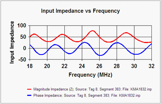
The 8-element LPA is model KMA1832, a custom design for the Reeve Observatory by KMA Antennas (www.kmaantennas.com/). Design frequency range is 18 ~ 32 MHz. It has a 14 ft double-boom made from 1 in. square aluminum tubes. The elements are stepped and made from round aluminum tube varying in diameter from 7/8 in. to 3/8 in. The characteristic impedance of the antenna is about 50 ohms (see VSWR and impedance charts below). A choke balun made from ferrite beads reduces common-mode currents on the transmission line.
The LPA antenna installation includes an antenna support structure, antenna rotator, and transmission line. Because of the overriding need to preserve local foliage, mainly for aesthetic reasons, the antenna installation is surrounded by deciduous trees and conifers and is far from optimum. The antenna site elevation is approximately 13 m AMSL and is about 200 m from the shore of Cook Inlet. Click here for a description of the antenna supporting structure (tower).
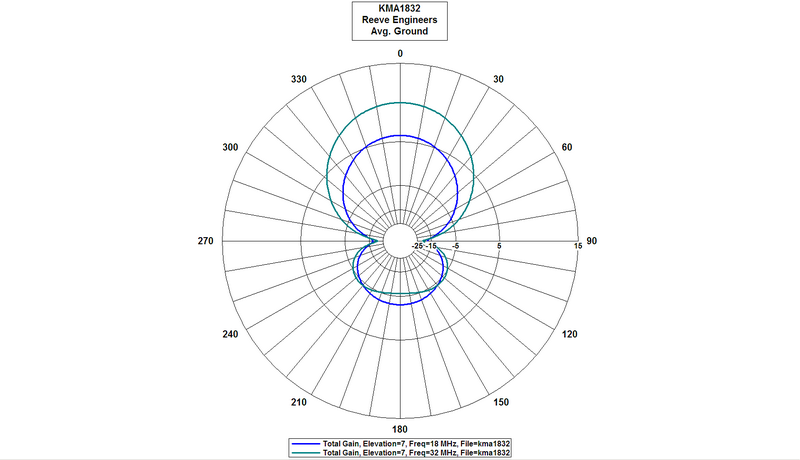
The LPA is a directional antenna with an a gain of approximately 7 to 10 dBi and 3 dB beamwidth of approximately 60 degrees, both determined from antenna models provided by the manufacturer. It is mounted on a rotatable shaft at the top of the tower approximately 13.8 m above ground level (AGL). The coaxial cable transmission line is 10 mm diameter Times Microwave LMR-400-DB (direct burial) and is approximately 50 m long.
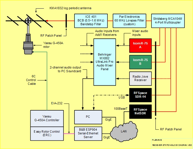
This antenna is our primary antenna for observations at HF. Although its design frequency range is 18 ~ 32 MHz we use it at lower HF frequencies. Because of high RF levels in the MF AM and VHF FM broadcast bands, we have to use considerable filtering to reduce the effects of intermodulation distortion in our receiver systems. External filters include a 0.5 ~ 1.6 MHz bandstop filter and 60 MHz lowpass filter. Also, to allow more than one receiver to be used with the antenna, we have installed a 4-port receiver multicoupler. The multicoupler provides a modest 2 dB gain across its useful frequency range of 500 kHz to 50 MHz, and it has an internal 50 MHz lowpass filter. The block diagram below shows the setup. Additional details on the receiver audio connections can be found here.
The four images below are from the antenna model (Nittany Scientific Products NEC-Win Plus). An animation of the azimuth patterns from 18 to 32 MHz also is provided below.


Animations showing how the azimuth and elevation patterns change with frequency are here:
- Azimuth pattern of main lobe in 1 MHz steps from 18 to 32 MHz
- Elevation in 1 MHz steps from 18 to 32 MHz
The rotator is a Yaesu G-450A, which is mounted on the tower at approximately 12.5 m AGL with a plate-mounted bearing located above it to provide lateral support. The rotator is controlled by an MDS RC1-G Digital Rotor Control through 50 m of 6-conductor outdoor control cable. The RC1-G serial port is connected to the laboratory Ethernet LAN through a B&B Electronics ESP901 EIA-232-to-Ethernet converter. This converter's virtual COM port mode allows the rotator to be controlled from a station PC using Ham Radio Deluxe software or YO3DMU PstRotatorAz software. Click here for a rotor control diagram.
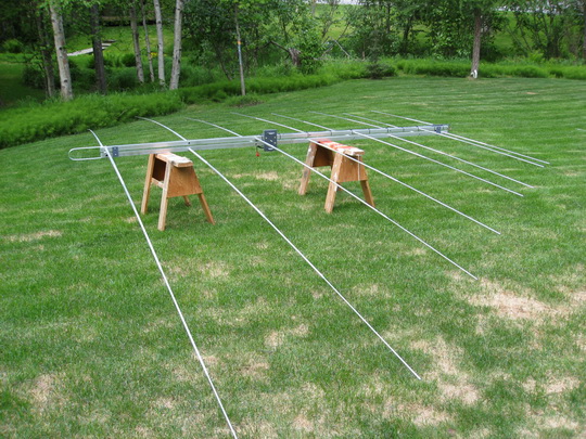
Antenna before being placed on tower
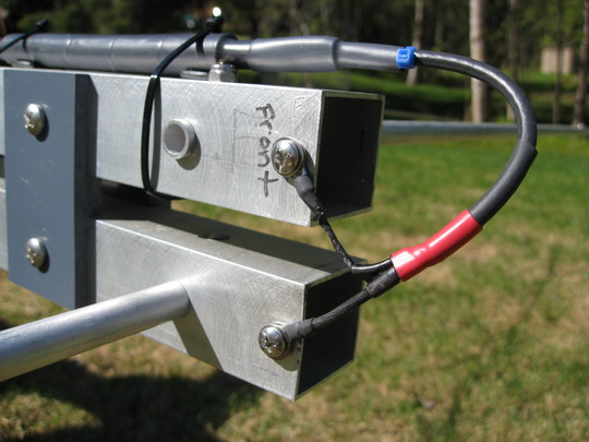
Front of antenna showing choke balun connection to the boom transmission line
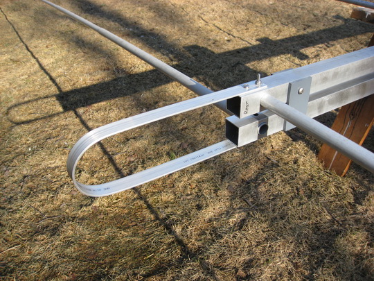
Inductive short circuit at rear of antenna to terminate the boom transmission line

Antenna on tower with gin pole and hoisting ropes. Antenna is in position and clamped
Installation completed June 8, 2010
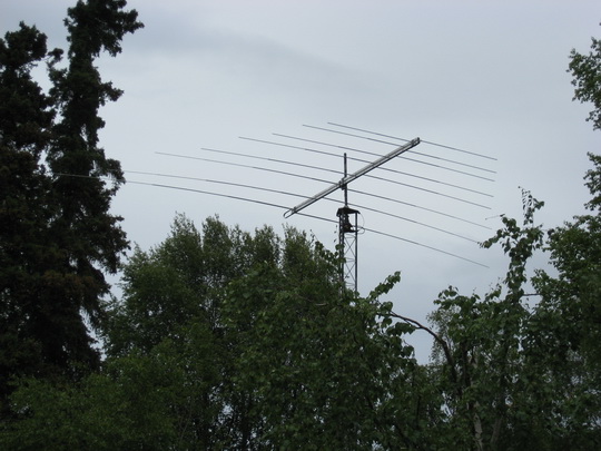
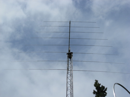
Antenna is above trees in immediate area
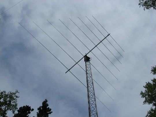
View against a partly cloudy sky pointed south
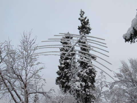
Above picture taken 12 December 2011
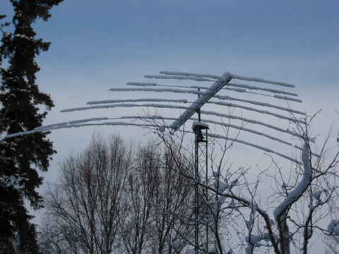
Above picture taken 26 November 2010

Above picture taken dead of winter 20 December 2010 during Moon eclipse