Magnetometer M1
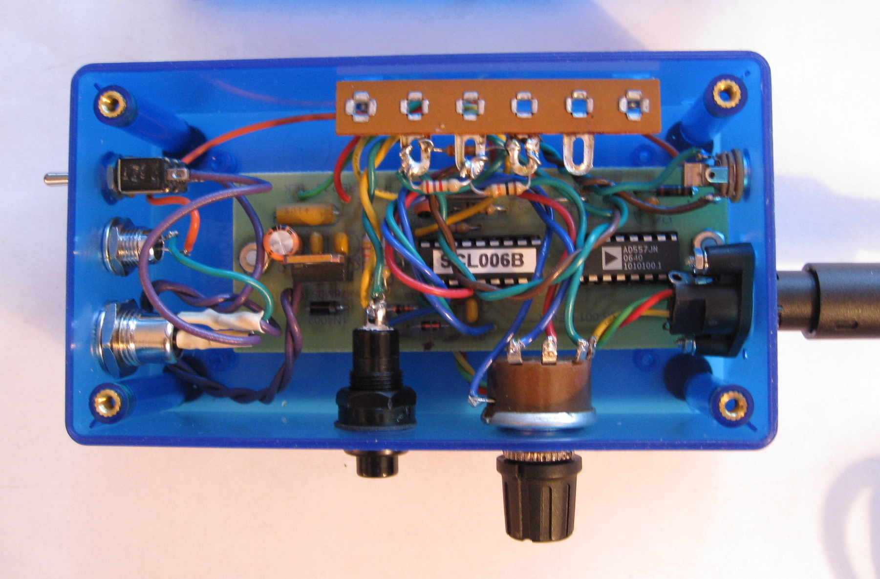
Signal conditioner printed circuit board; the SLC-006B ASIC and AD557 DAC are clearly visible.

Signal conditioner module with everything mounted
in a plastic case. On the left are the power switch, power
ON indicator LED and coaxial dc power jack. On the right are the mini-DIN
connector for the sensor and a
3.5 mm phone jack for connection to the data logger. The controls on the
lower side of the module are the center
scale reset switch (left) and 4-position sensitivity control rotary switch
(right).

FGM-3 magnetometer sensor mounted of perforated
board for testing. The electrolytic capacitor provides
noise filtering at the dc power input lead of the sensor. The mini-DIN
connector connects to the signal conditioner
module.
