Model M1 Magnetometer
The model M1 magnetometer data acquisition system was built and place in service around January 19, 2009.
Due to the high seismic activity in the area of Redoubt volcano and the predicted volcanic activity approximately 171 km southwest of our observatory, we setup the unit to log continuously on January 23, 2009. We hoped to detect and capture geomagnetic disturbances but the magnetometer lacked sensitivity for this application.
The model M1 consists of the following items:
- Sensor: Speake & Co Llanfapley FGM-3 or FGM-3h
- Signal conditioner module: Shop built, based on the Fat Quarters Software PCB and Speake & Co Llanfapley SLC-006B ASIC
- Data logger: LabJack U3-LV
- PC software: AzeoTech DAQFactory Express
The SLC-006B ASIC provides basic timing/counting functions to convert the width modulated (PWM) output of the magnetometer sensor to 8-bit digital values. The ASIC data outputs are connected to an Analog Devices AD557 digital-analog converter (DAC), which provides a dc voltage related to the sensor output.
The DAC dc output may be displayed directly on a panel meter, but this option is not presently used. Instead, the DAC output is conditioned (voltage level shifted) and connected to a LabJack U3-LV data logger for display and logging on a PC. The U3-LV also has an internal temperature sensor, which was used in experiments to determine the temperature sensitivity of the sensor (follow this link). LabJack's DAQFactory Express software is used on the lab PC to control the logger and display and log the data.
Click here for a block diagram of the data acquisition system.
Click here for a schematic of the signal conditioner module and related components.
Click here for photographs of the various system components.
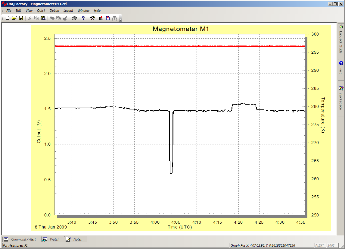
The screenshot below shows the data acquisition display. The magnetometer output is the black line and uses the left vertical axis. The magnetometer output is uncalibrated in this screenshot and is given in volts (the full-scale range is 0 - 2.0 vdc). The data logger temperature is the red line and uses the right vertical axis. The signal conditioner module is set to sensitivity position 2 (1 is least sensitive and 4 is most sensitive) - see schematic. The sensor is setup in an indoor environment, oriented east-west, with no effort made to remove ferromagnetic material from its environment. A ballpoint pen was placed about 1/6 meter from the sensor at about 0404 UTC and caused the downward notch. The pen was moved to a different location near the sensor at around 0418 to 0424 UTC causing the upward notch. The time scale is in UTC; local time is UTC - 9, so 0400 UTC is equivalent to 1900 Alaska Standard Time.