Tower-Mounted Amplifier Assembly ~ TMA-1/TMA-2 with LPC
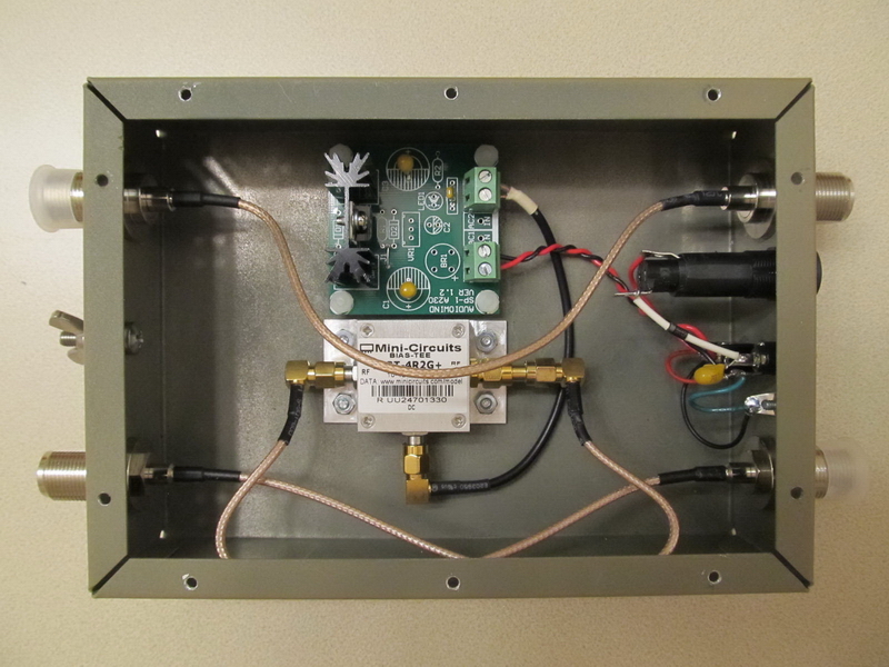
The Tower-Mounted Amplifier components are enclosed in a weatherproof polyester enclosure. A lightning arrestor assembly (black object lower-left) with a type-N coaxial connector connects to the antenna. The amplifier module is just above and left of the arrestor and its output is connected to a Mini-Circuits VLM-33+ limiter and then to the bias-tee power coupler. The limiter prevents momentary surge voltages on the bias-tee RF port from damaging the amplifier. The other side of the bias-tee connects directly to a type-N coaxial connector (lower-right), which carries RF back to the LPC and dc from the LPC to the TMA. The dc output from the bias-tee is connected to a linear regulated power supply, which supplies 3.3 Vdc to the amplifier module.

TMA Features:
- Weatherproof polyester enclosure;
- Powering through RF coaxial cable;
- Provisions for bonding and grounding using stainless-steel fasteners;
- The enclosure includes a small hole on the bottom to prevent pressure build-up due to temperature changes and for drainage. The hole is screened against insect intrusion;
- Pilot holes have been drilled (and plugged) for a second lightning arrestor and unpowered transmission line feed to a second receiver. The holes may be enlarged with a common hole saw. An upgrade kit is available;
- All internal RF connections are through type-SMA connectors and RG-316/U coaxial cable and all power connections are through RG-174/U coaxial cable;
- Internal power supply consists of only four electronic components, three filter capacitors and fixed voltage regulator integrated circuit (photograph above shows a prototype with a variable power supply);
- The aluminum chassis is painted with self-etching primer;
- The enclosure dimensions are nominally 8 in high x 6 in wide x 4 in deep (approximately 200 mm x 150 mm x 100 mm) not including the cover.
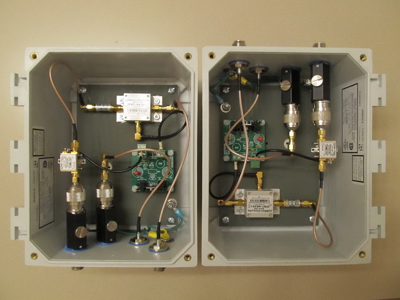
LNA Power Coupler Assembly
The LNA Power Coupler has provisions for powering and connecting two low noise amplifiers in a TMA. One transmission line carries RF from an antenna and a low noise amplifier in the TMA back to a receiver. This transmission line also carries dc for powering up to two low noise amplifiers in the TMA. Another transmission line carries RF from a second antenna and optional low noise amplifier in the TMA back to a second receiver. This bypass transmission line is unpowered.
LPC Features:
- Stainless-steel fasteners for connecting an earth bonding conductor;
- Power On/Off switch, LED power indicator and coaxial power connector (2.1 x 5.5 mm, center positive);
- A linear power supply supplies 8.0 Vdc through the bias-tee power coupler to a type-N coaxial connector. The input voltage of the LPC is nominal 11 ~ 15 Vdc. RF from the tower-mounted amplifier is coupled back to the LPC through the same connector;
- All internal RF connections are through type-SMA connectors and RG-316/U coaxial cable and all power connections to the bias-tee are through RG-174/U coaxial cable;
- The primer and paint has been removed with sandpaper under the mounting hole for the bias-tee to ensure adequate chassis bonding;
- The aluminum enclosure is painted with self-etching primer and top-coated with dark taupe enamel;
- The enclosure bottom plate (not shown) is fastened with eight machine screws;
- The enclosure is 7 in long x 5 in wide x 2 in high (approximately 178 mm x 127 mm x 50 mm).
Additional images

Typical Tests and Measurements

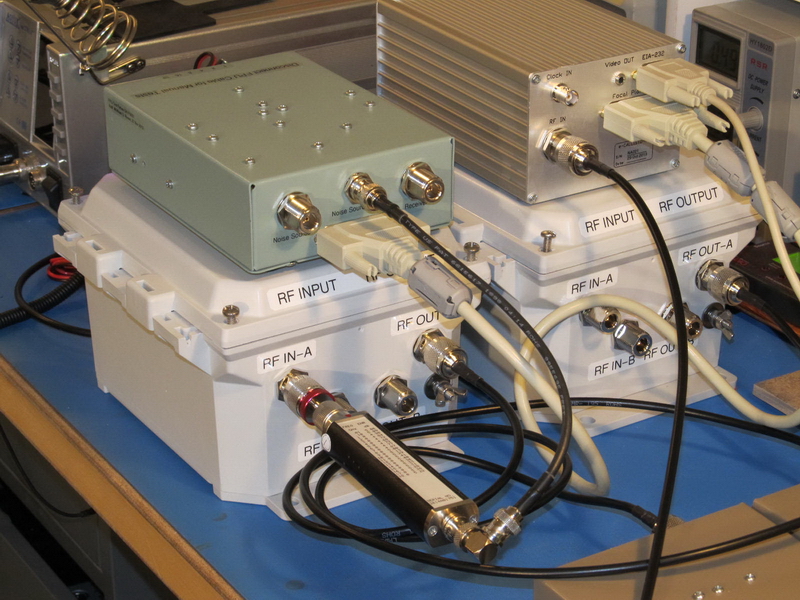
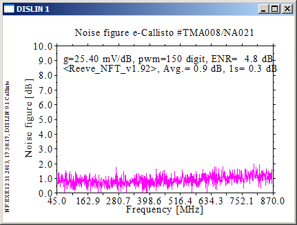
Noise figure: The measured noise figure of the TMA in combination with the LPC and a CALLISTO Receiver is shown below. The measurement was made at 1000 points. It is typical and is influenced mostly by the low noise amplifier module in the TMA. The measurement was made with short interconnecting cables between the TMA and the LPC and between the LPC and CALLISTO Receiver. The calibrated noise source (Agilent 346A with nominal 5 dB ENR) was connected directly to the RF input of the TMA.
Gain: In addition to the noise figure, the gain of the TMA and LPC assemblies are measured in combination using a spectrum analyzer with a tracking generator. The plot below shows the results of measurements from 10 MHz to 1 GHz with -30 dBm tracking generator level (markers are at 45, 457.5 and 870 MHz). At lower frequencies, the measured gain 21.29 dB is nominally the same as indicated in the amplifier datasheet. At higher frequencies there are implementation losses due to cables and the two bias-tees. The gain at the higher frequencies will be less than shown in the plot below when longer interconnecting cables are used.
![]()
Packing and Shipping Note: Package dimensions for TMA/LPC: 16x12x10 in, 7.5 lb