TMA2Q/LPC2Q Tower-Mounted Amplifier Assembly and Quadrature Power Coupler Assembly
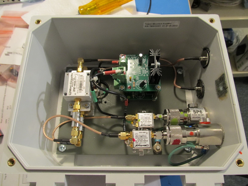
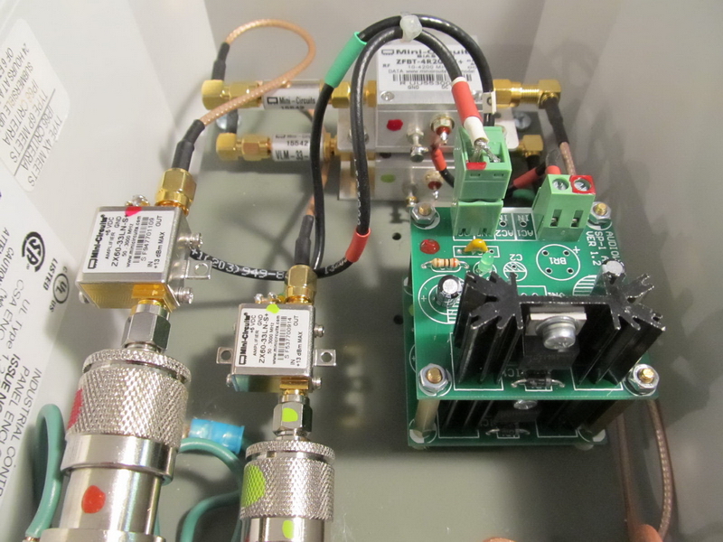
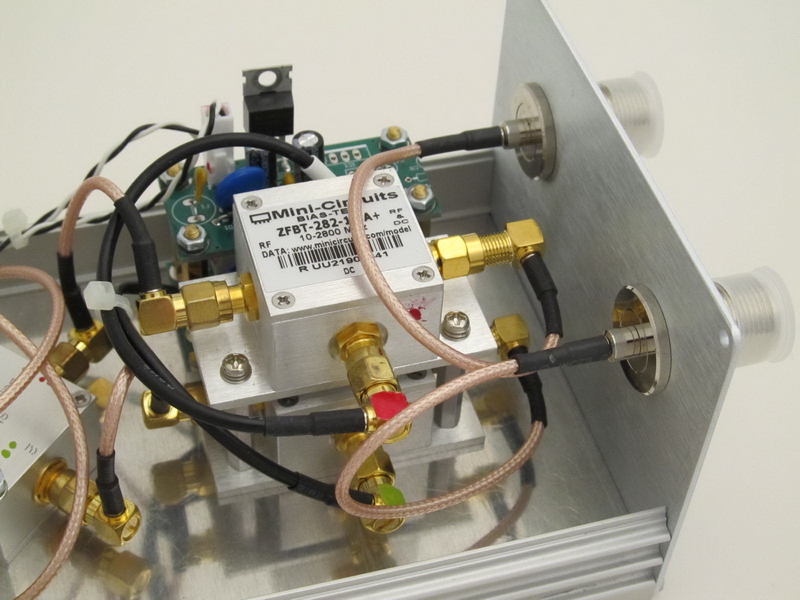
The Tower-Mounted Amplifier components for two LNA circuits are enclosed in a weatherproof polyester enclosure. Two lightning arrestor assemblies, one for each circuit, connects to the antenna. The amplifier modules are above and left of the arrestor and their outputs are connected to Mini-Circuits VLM-33+ limiters and then to the bias-tee power couplers. The limiters prevent momentary surge voltages on the bias-tee RF ports from damaging the amplifiers. The other side of the bias-tees connect directly to a type-N coaxial connector, which carries RF back to the LPC2Q and dc from the LPC2Q to the TMA2Q. The dc outputs from the bias-tees are connected to linear LDO regulated power supplies, which supply 3.3 Vdc to the amplifier modules.
TMA2Q Features:
- Weatherproof polyester enclosure;
- Powering through RF coaxial cable;
- Provisions for bonding and grounding using stainless-steel fasteners;
- The enclosure includes a small hole (1 mm) on the bottom to prevent pressure build-up due to temperature changes and for drainage;
- All internal RF connections are through type-SMA connectors and RG-316/U coaxial cable and all power connections are through RG-174/U coaxial cable;
- Independent internal power supplies consists of only a few electronic components, three filter capacitors and fixed voltage regulator integrated circuit, a power indicating LED and associated current limiting resistor;
- The aluminum chassis is painted with self-etching primer;
- The enclosure dimensions are nominally 8 in high x 6 in wide x 4 in deep (approximately 200 mm x 150 mm x 100 mm) not including the cover.
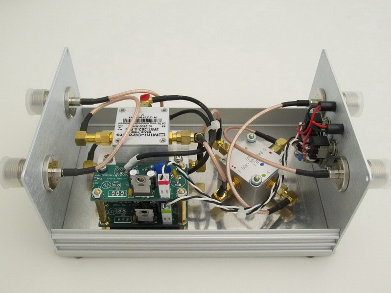
LPC2Q Quadrature LNA Power Coupler Assembly
The Quadrature LNA Power Coupler has two independent power supplies for powering the low noise amplifiers in the TMA2Q, two independent RF and powering paths to the TMA2Q and two quadrature RF paths from the LPC2Q to the two receivers.
LPC2Q Features:
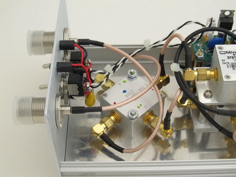
- Power On/Off switch and LED power indicator for each circuit and coaxial dc power connector (2.1 x 5.5 mm, center positive);
- Linear power supplies provide 8.0 Vdc through the bias-tee power couplers to type-N coaxial connectors. The input voltage of the LPC2Q is nominal 11 ~ 15 Vdc. RF for each circuit from the TMA2Q is coupled back to the LPC2Q through the same connector;
- All internal RF connections are through type-SMA connectors and RG-316/U coaxial cable and all power connections to the bias-tee are through RG-174/U coaxial cable;
- The extruded aluminum enclosure is the same size and type as used with the Callisto receiver
- Silk-screened end panels;
Additional images

Typical Tests and Measurements
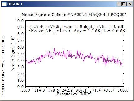
Noise figure: The measured noise figure of the TMA2Q in combination with the LPC2Q and a CALLISTO Receiver is shown below. The measurement was made at 200 points. It is typical and is influenced mostly by the low noise amplifier module in the TMA. The measurement was made with short interconnecting cables between the TMA2Q and the LPC2Q and between the LPC2Q RF Output and CALLISTO Receiver. The calibrated noise source (Agilent 346A with nominal 5 dB ENR) was connected directly to the RF input of the TMA2Q. Each individual amplifier has a noise figure of about 1 dB but it is degraded when measured at the output of the quadrature coupler. The Y-Factor method is used and the coupler combines the cold noise from both amplifiers but only the hot noise from one amplifier leading to 3 to 4 dB higher measured system noise figure.
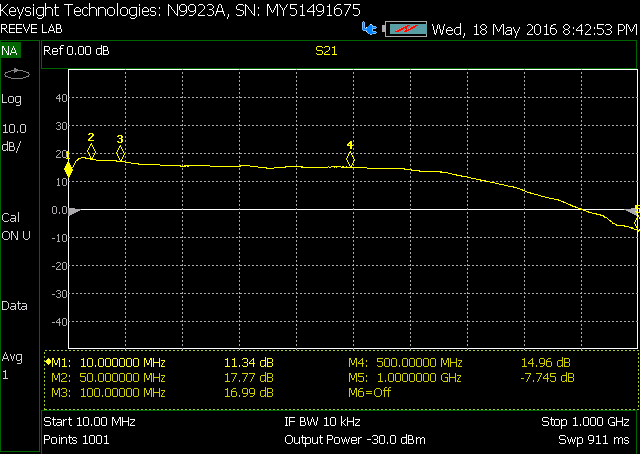
Gain: The gain of the TMA2Q and LPC2Q combination is measured using a vector network analyzer. The plot below shows the results of measurements from 10 MHz to 1 GHz with -30 dBm input level (markers are at 10, 50, 100, 500 and 1000 MHz). At lower frequencies, the measured gain approximately 17.8 dB and includes the splitting loss of the quadrature coupler (3.5 to 4.0 dB). At higher frequencies there are additional implementation losses due to cables and the two bias-tees. When longer interconnecting cables are used, the gain at the higher frequencies will be less than shown in the plot below.
Packing and Shipping Note: Package dimensions for TMA2Q/LPC2Q: 16x12x10 in, 10.5 lb