CALLISTO Receiver Construction
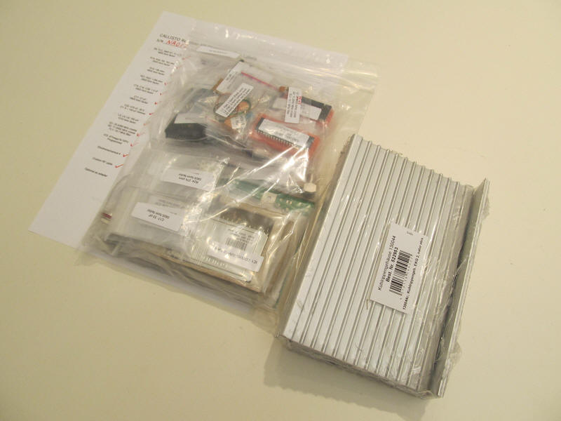
The CALLLISTO kit includes
bagged components and aluminum enclosure. The CALLISTO may be purchased
ready-built and tested, in which case it is built from the kit.
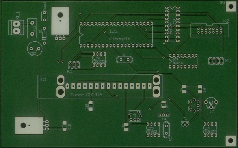
Printed circuit board -
Top, without components. Layout is well-designed
with
separation of RF and IF components
from digital, power and baseband components.
The coupling/impedance matching
transformers for 36.13 and
10.7 MHz IF are in the lower-right corner
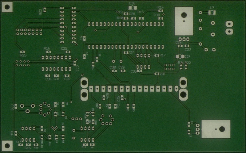
Printed circuit board -
Bottom. Most passive components (resistors, capacitors, inductors) are mounted
on the
bottom.
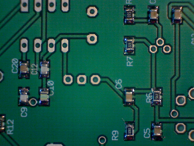
Close-up image of some surface mount devices, size 0805. All ready-built and tested receivers are hand-built.
Completed receiver
showing the rear panel (left) with input/output connectors. Included are antenna and
clock RF
connectors, video (audio)
connector, EIA-232
serial port
connector (DB-9F) and Focal Plan Unit connector (DB-25F).
The front panel (right) has a dc power jack,
On/Off switch and
power indicating LED.
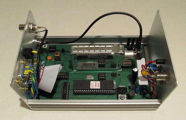
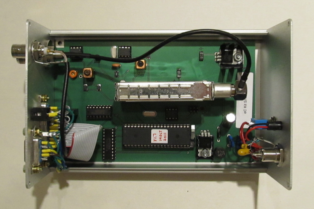
Interior view of completed receiver, ready for
testing. The silver module in the middle is the tuner, which
includes RF input and down-conversion functions (see next image). The tuner is a Phillips
CD1316L/IVP-3 with
IEC (PAL) connectors
for RF input/RF output. The RF output connector on the tuner is not used.
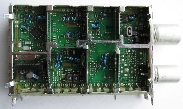
Interior view of tuner that had to be replaced.
RF input is the compartment at the upper-right and RF
output (not used) is the compartment on the lower-right. The tuner is a
digitally controlled analog RF device.
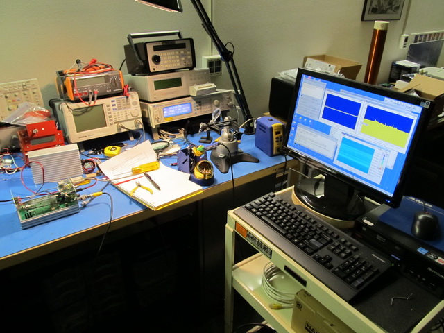
Receiver (left) on test bench with Callisto software running on lab PC (right)