Long Wavelength Array Active Crossed-Dipole Antenna
If you are interested in ordering the crossed-dipole antenna and associated active balun assembly described below, click here.
Description
The first Long Wavelength Array (LWA1) is located about 65 km west of Socorro, New Mexico. The LWA antenna has many applications beyond large arrays. These use from one to eight antennas for solar radio observations and radio sky surveys. The LWA antenna is a receive-only antenna with a design frequency range of about 5 to 90 MHz.
The LWA antenna is an inverted-V design with elements that consist of triangular sloping wings or blades as shown immediately below. An active balun, called Front End Electronics (FEE), shown in the block diagram below, converts the balanced dipole to unbalanced 50 ohm impedance for connection to a coaxial cable transmission line and also provides approximately 37 or 34 dB gain depending on the FEE version. The FEE is powered through the coaxial cable by a bias-tee arrangement in the equipment enclosure. A FEE consists of two identical printed circuit boards, one for each dipole in the crossed-dipole antenna.
The original design documents for the entire LWA antenna system are accessible through the LWA website. Also, the following paper describes the details and motivations behind the antenna design in 2012 and provides many details such as wind survivability, construction and installation: A Wide-Band, Active Antenna System for Long Wavelength Radio Astronomy by Brian Hicks at the Naval Research Laboratory (and others).
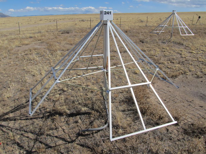
One of 257 Long Wavelength Array antennas at LWA Station 1 in New Mexico USA. The active balun is in the rectangular enclosure at top of antenna. The top of the active balun enclosure is 1.52 m above ground level. Each antenna element consists of a triangular aluminum frame sloping down from the top and supported from the center post by non-conductive horizontal fiberglass rod braces. The frames, or blades, are welded 3/4 in (19 mm) square aluminum tubing. Each element is 1.5 m long x 0.8 m wide. At the base of each antenna is a 3 m x 3 m galvanized wire mesh (“chicken wire”) ground screen. (Image © 2013 W. Reeve)
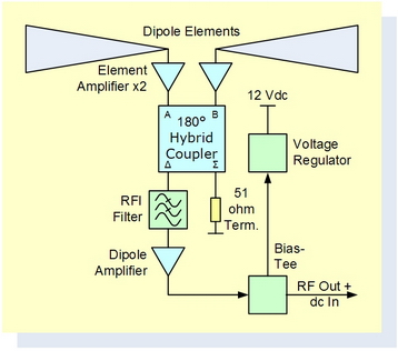
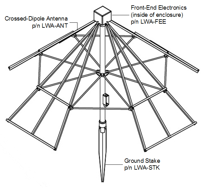
Active balun block diagram and antenna line drawing. The currents produced in each dipole element are coupled directly to an amplifier with about 25 dB gain. The amplified outputs from the two elements are connected to a 180° hybrid coupler that combines them in phase. The output from the hybrid coupler is filtered and then amplified by about 12 dB. The total gain from the elements to output is about 35 dB, and the reported noise temperature is 250 K (2.7 dB noise figure). The active balun has a usable frequency range of about 1 MHz to 115 MHz. Line drawing shows the major assemblies that may be ordered for the antenna. (Image © 2014 W. Reeve)
Design and Construction
The LWA antenna is not our design. The original design documents are publicly available as mentioned above. Our antennas and FEE assemblies are identical to those used in the LWA antennas.
Transmission Line, Power and Protection Considerations
The Front-End Electronics are powered through a bias-tee located at or near the receiver equipment. For additional information, see Transmission Line, Power and Protection Considerations for the LWA Antenna System. An LWA Power Coupler, specifically designed for use with the LWA antenna that we sell, is now available - see LWA ordering page. The LWAPC will be available with or without a quadrature coupler for discrimination of polarization (see Applications for Circular Polarization below).
Antenna Pattern
The sloping elements provide an omni-directional dome shaped antenna pattern. Overall, the pattern provides close to horizon-to-horizon coverage with decreased response at low elevation angles as shown below. The non-directional characteristic of this antenna means that it can be more susceptible to radio frequency interference than a directional antenna. In its original design as an array of antennas, post-processing beam forming is used when directional characteristics are needed.
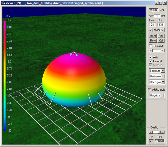
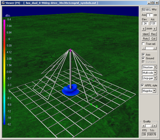
3-dimensional LWA antenna pattern simulations at 50 MHz showing response to Right-Hand Circular Polarization (left) and Left-Hand Circular Polarization (right). Other frequencies in the design frequency range are similar. Patterns were produced by 4NEC2.
Applications for Circular Polarizations
A crossed-dipole antenna, such as the LWA antenna, can be setup to discriminate right-hand circular or left-hand circular polarization by combining the output of each dipole in a 90° hybrid coupler as shown below. For additional information, see Introduction to Radio Wave Polarization and Antenna Application for the Quadrature Coupler.
Our primary application for the active crossed-dipole antenna is reception of solar radio bursts, in which case we use the antenna with the CALLISTO instrument described here and the model UPC-1 Up-Converter described here. When used with the CALLISTO instrument alone, the usable frequency range is 45 to 90 MHz, but the range may be extended to 20 to 90 MHz with the UPC-1 Up-Converter.

Active crossed-dipole antenna with CALLISTO receiver. Upper: Frequency range 45 to 90 MHz. Lower: Frequency range 10 to 90 MHz. (Image © 2014 W. Reeve)
If you are interested in ordering the crossed-dipole antenna and associated active balun described above, click here.
LWA TV on the Raspberry Pi Computer
Read how to use the Raspberry Pi computer to download and display near real-time radio activity from the LWA Station 1 in New Mexico USA. A preprogrammed micro-SD card with the LWA TV Graphical User Interface is available here.
Summary List of Documents Associated with Long Wavelength Array Antenna
Antenna Application for the Quadrature Coupler
Introduction to Radio Wave Polarization
Long Wavelength Array Power Coupler Installation and Operation
Modeling the Long Wavelength Array Crossed-Dipole Antenna
Transmission Line, Power and Protection Considerations for the LWA Antenna System
Update ~ LWA TV on the Raspberry Pi ~ Add LWA-SV
